 Online chat
Online chat
Online chat
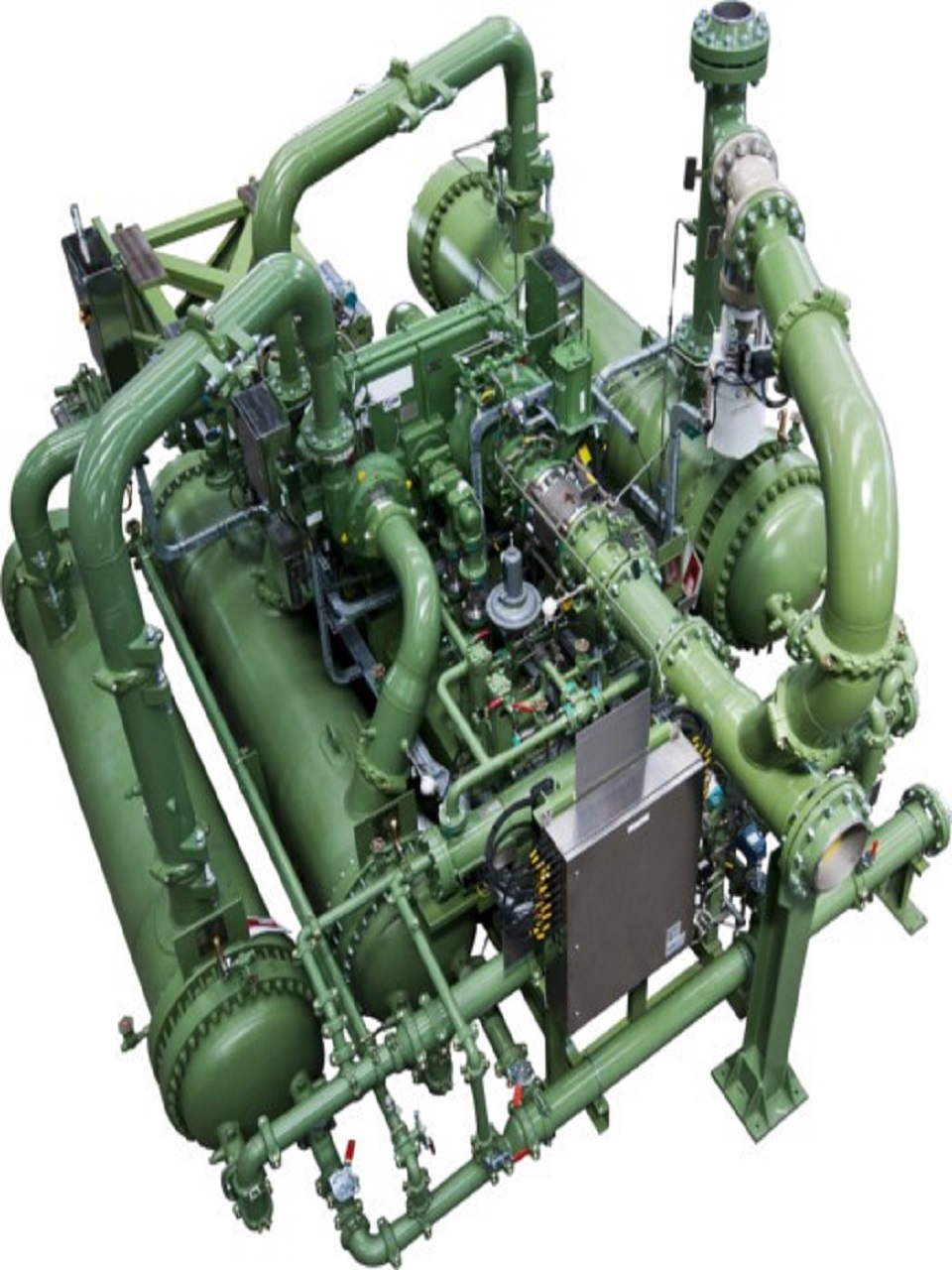


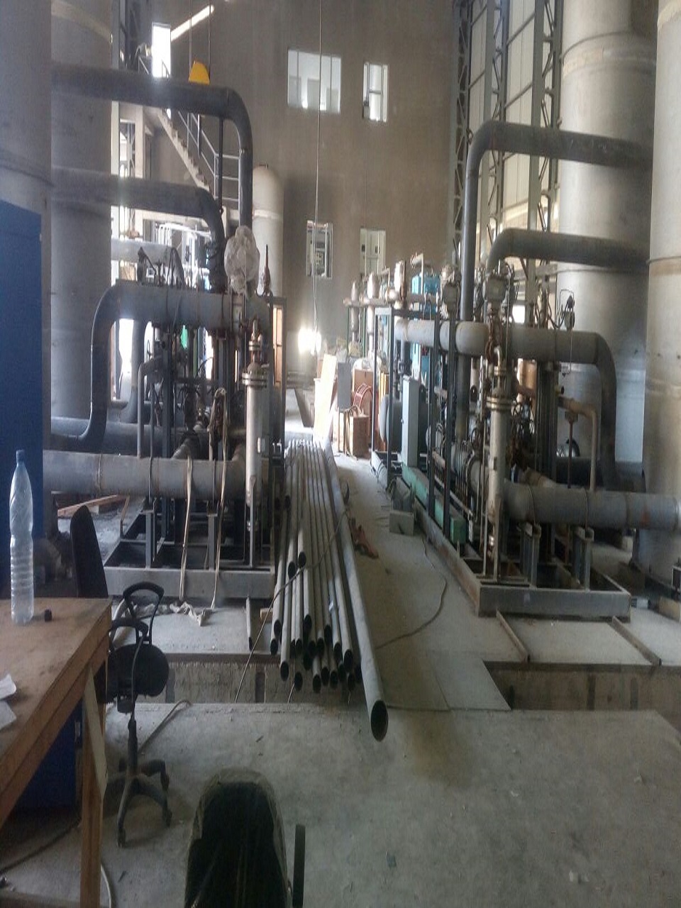
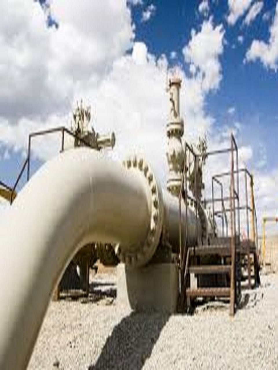
Air Compression and Air Filtration system is used to Generate Feed air for Air Separation Gas Plants.
The air is filtered to remove dust and dirt before it enters the Main Air Compressor (MAC). The MAC is usually centrifugal compressor powered by an electric motor. The compressor usually has its own lube oil system. Between the compressor stages are intercoolers that cool the air. When the air cools, water vapor condenses and is removed through traps
We have expert team of Rotary Machine to selects the perfect matching compressor of ASU gas Plants, In general we selects Centrifugal Compressor to generate the feed air at 7 Kg/ cm2 with 110 Deg cent
We have direct association with Ingersoll rand, Atlas Copco and other Manufacturers of Centrifugal Compressor


 "Pinterest")
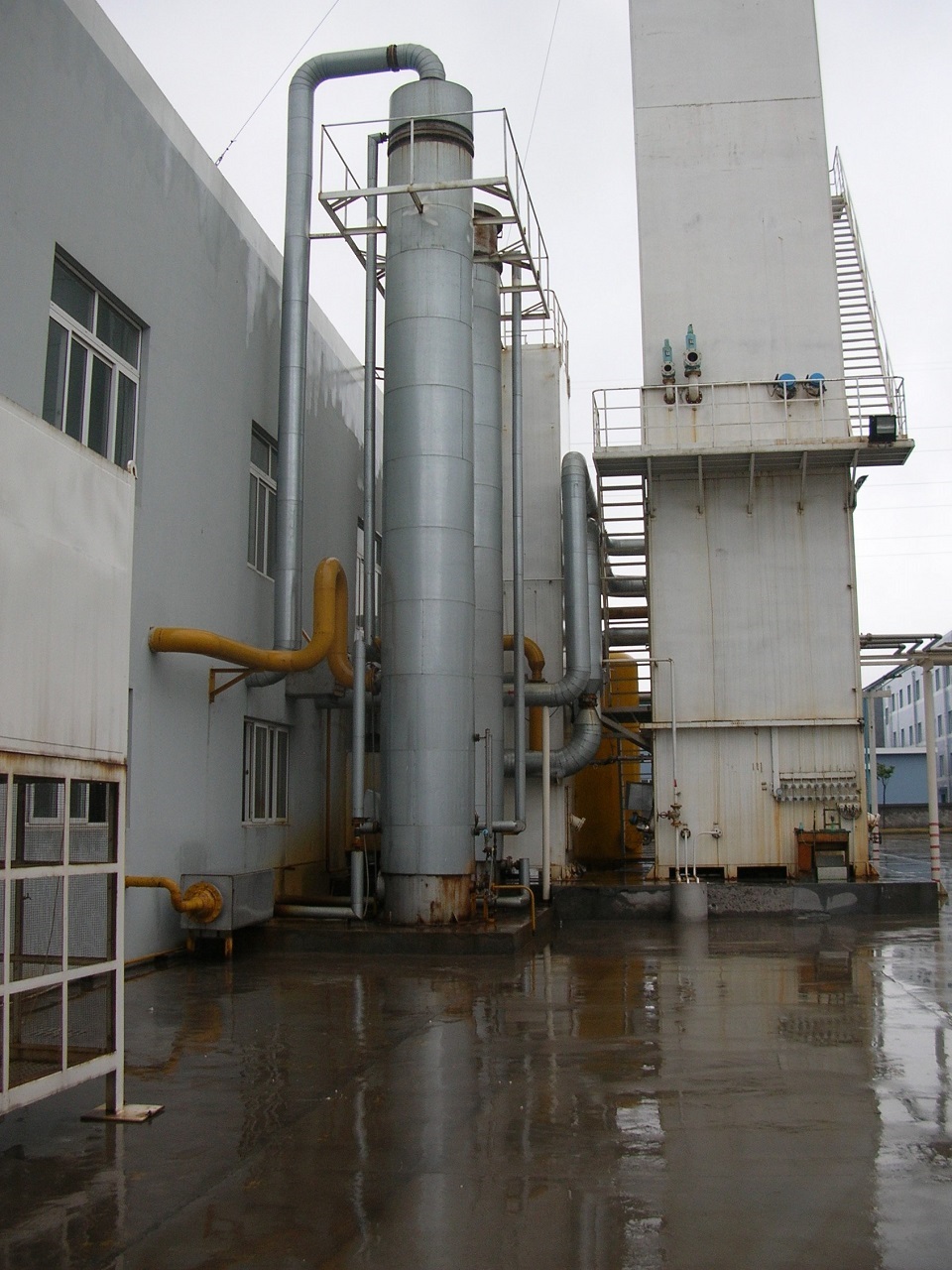
This system consists of the air cooling tower, water cooling tower and four water pumps to reduce the Temperature from 110 Deg Cent to 16 Deg Cent.
The air cooling tower is of the packing type with two layers of packing material. The air delivered to the bottom of the air cooling tower from the user’s piping network passes through the packing layers from the bottom to the top and is cooled by the water flowing from the top to the bottom with part of NOx?SO2 , C1+ and other harmful impurities removed. Finally, the air enters the molecular sieve purification system after passing through the wire mesh separator. The air leaves the air cooling tower at a temperature of approximately 15?. There are two streams of water in the air cooling water. The lower stream is the cooling water from the chilling water tower provided by the user, which enters the middle section of the air cooling tower after being pressurized by the recycling water pump to converge with the chilling water flowing from the top to the bottom and finally returns to the chilling water tower. The upper stream is the chilling water from the chilling water tower, which is delivered to the top of the air cooling tower by the chilling water pump after having conducted the heat and mass exchange in the cooling water tower with the redundant pure nitrogen and waste nitrogen from the rectification column.


 "Pinterest")
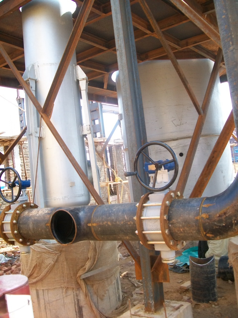
This system is comprised of two absorbers and two electric heaters. By this system air purified by the absorbers is below -65. The purified air has a content of CO2 1 ppm and its temperature is 21
The absorbers are of a vertical & double-bed structure. The upper bed contains molecular sieve while the lower bed activated alumina and the two absorbers work alternatively. Part of the air from the air cooling tower, after being rid of free water, CO2 and other Cn Hm via the adsorbed, enters the cold box and the braking compressor (i.e. the booster) of the turbo-expander while the rest is used as the instrument air. When one adsorbed is in operation, the other is being regenerated and cooled. The waste nitrogen from the cold box enters the adsorbed for regeneration after being heated to 180? by the electric heater to remove water and CO2 and then is vented to the atmosphere.


 "Pinterest")
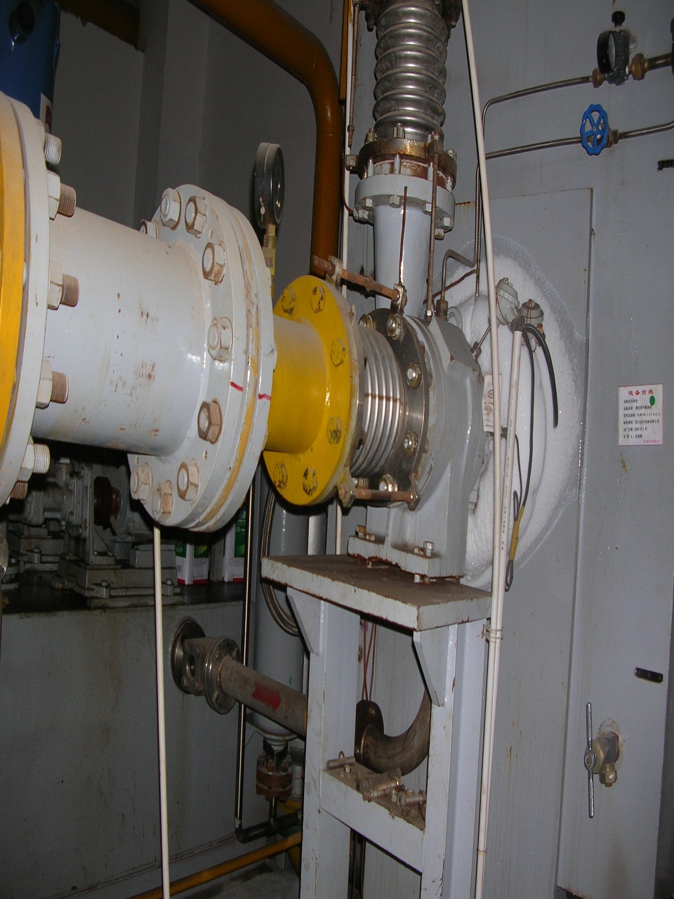
This system consists of two turbo-expander units, two after-coolers for the braking compressors and two oil supply devices.
The clean air from the molecular sieve absorber enters the braking compressor to consume the work generated by the expander and at the same is pressurized. After being cooled to about 40? in the after-cooler of the braking compressor, the boosted air enters the main heat exchanger to be cooled to a 165 K and then goes into the expander for expansion. The expanded air is further cooled in the heat exchanger and then enters the upper column for rectification. The remainder of the air is directly sent to the main heat exchanger to be cooled to its dew-point of about 100 k and then enters the lower column for rectification.


 "Pinterest")
This system is mainly made up of the lower column, the main condenser/ evaporator and the upper column.
The feed air from the purification system is rectified in the lower column and then nitrogen is obtained at its top. Small part of the gained nitrogen is used as the heat source for the fine argon column while the rest is condensed in the main condenser/evaporator. Part of the condensed liquid from the main condenser/evaporator is used as the reflux of the lower column and the rest is throttled and delivered to the upper column as the reflux after being cooled in the sub-cooler. The oxygen-enriched liquid air obtained at the bottom of the lower column is throttled to the middle of the upper column for rectification after being cooled in the sub-cooler. After being rectified in the upper column, the product nitrogen is gained at the top of the upper column while the waste nitrogen is obtained at the upper section of the upper column. The nitrogen gas and waste nitrogen are reheated in the sub-cooler and main heat exchanger. After being reheated, part of the nitrogen gas is delivered to the pipe network of the user while the rest is sent to the water cooling tower for refrigeration; part of the waste nitrogen is used as the regenerating gas while the rest is also transferred to the water cooling tower for refrigeration. The oxygen obtained at the bottom of the upper column is delivered to the piping network of the user after being heated in the main heat exchanger. The liquid oxygen is sent to the storage system of the user after being extracted from the bottom of the main condenser/evaporator and the liquid nitrogen is extracted to the storage system of the user after being sub-cooled.


 "Pinterest")
This system is composed of the crude argon column I, crude argon column II, crude argon condenser and fine argon column.
The stream of argon fraction extracted from the middle section of the upper column enters the crude argon column I to be rectified to decrease its oxygen content. The reflux for the crude argon column I is the crude liquid argon that is delivered by the liquid pump after being extracted from the bottom of the crude argon column II. The liquid at the bottom of the crude argon column I returns to the upper column for rectification. The gas extracted from the top of the crude argon column I enters the bottom of the crude argon column II for further separating oxygen and argon, so that the crude argon gas with a content of oxygen ?2 ppm is obtained, which flows back to the crude argon column II as reflux after being condensed into liquid by the crude argon condenser. The cold source of the crude argon condenser is the liquid air extracted from the sub-cooler, which returns to the proper part of the upper column for rectification after heat exchanging with the crude argon gas and being evaporated.


This system consists of Oxygen and Nitrogen Gas Compressor with its isolation and other accessories, Discharge Pressure of Product compressor depends upon process requirements.


 "Pinterest")
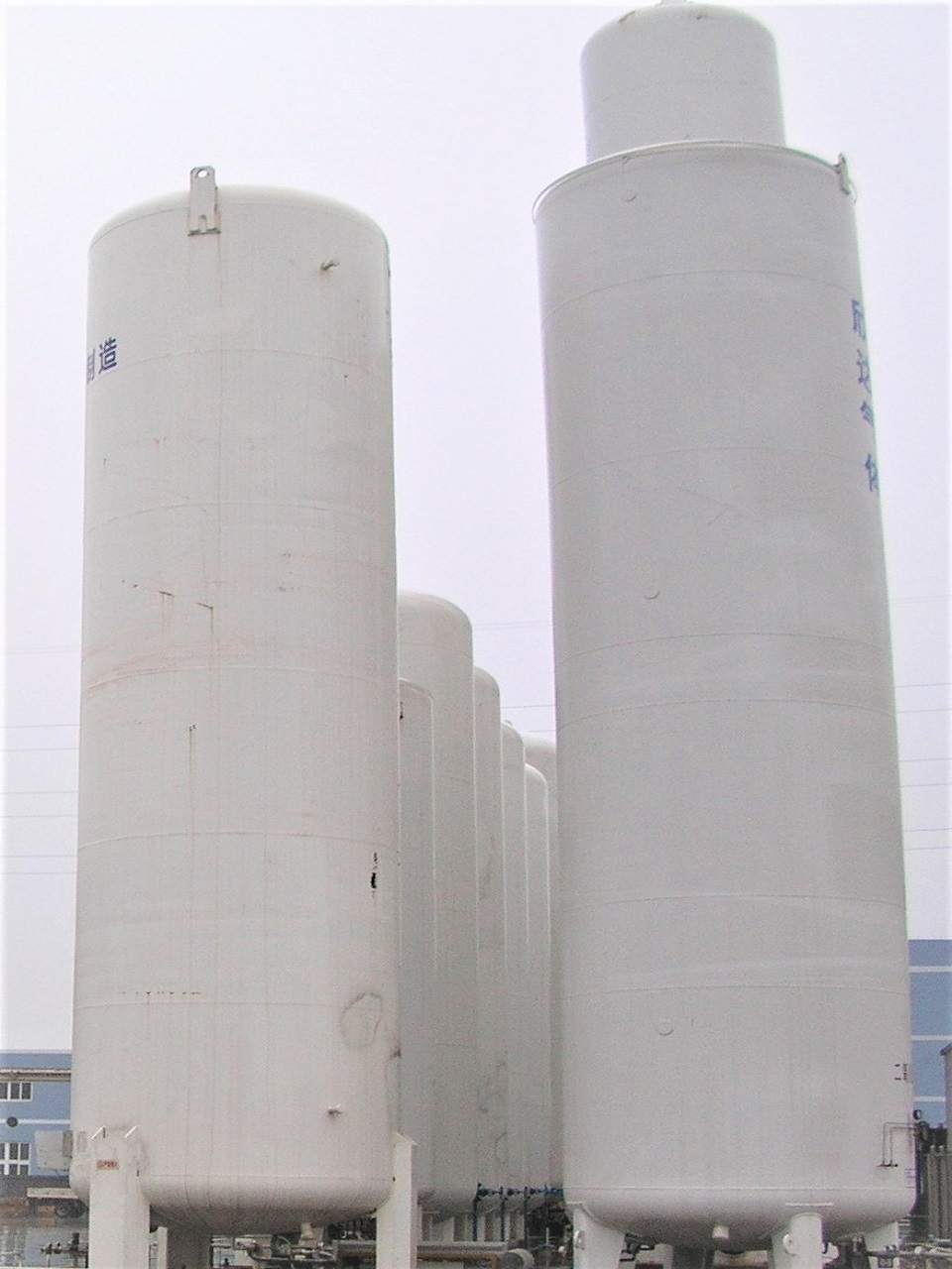
Gas storage system Consist of Storage tanks and its isolation system this size depends upon process requirements Gas storage system Consist of Storage tanks and its isolation system this size depends upon process requirements.


 "Pinterest")
Pressure reducing system consist of control Valve and isolation valves with its measuring and control instruments as per requirements of process and it is being used for Reducing the pressure as per requirements.
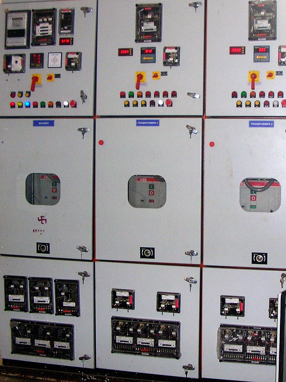


Electrical System consist of PCC & MCC panel with its transformer and other item to control system
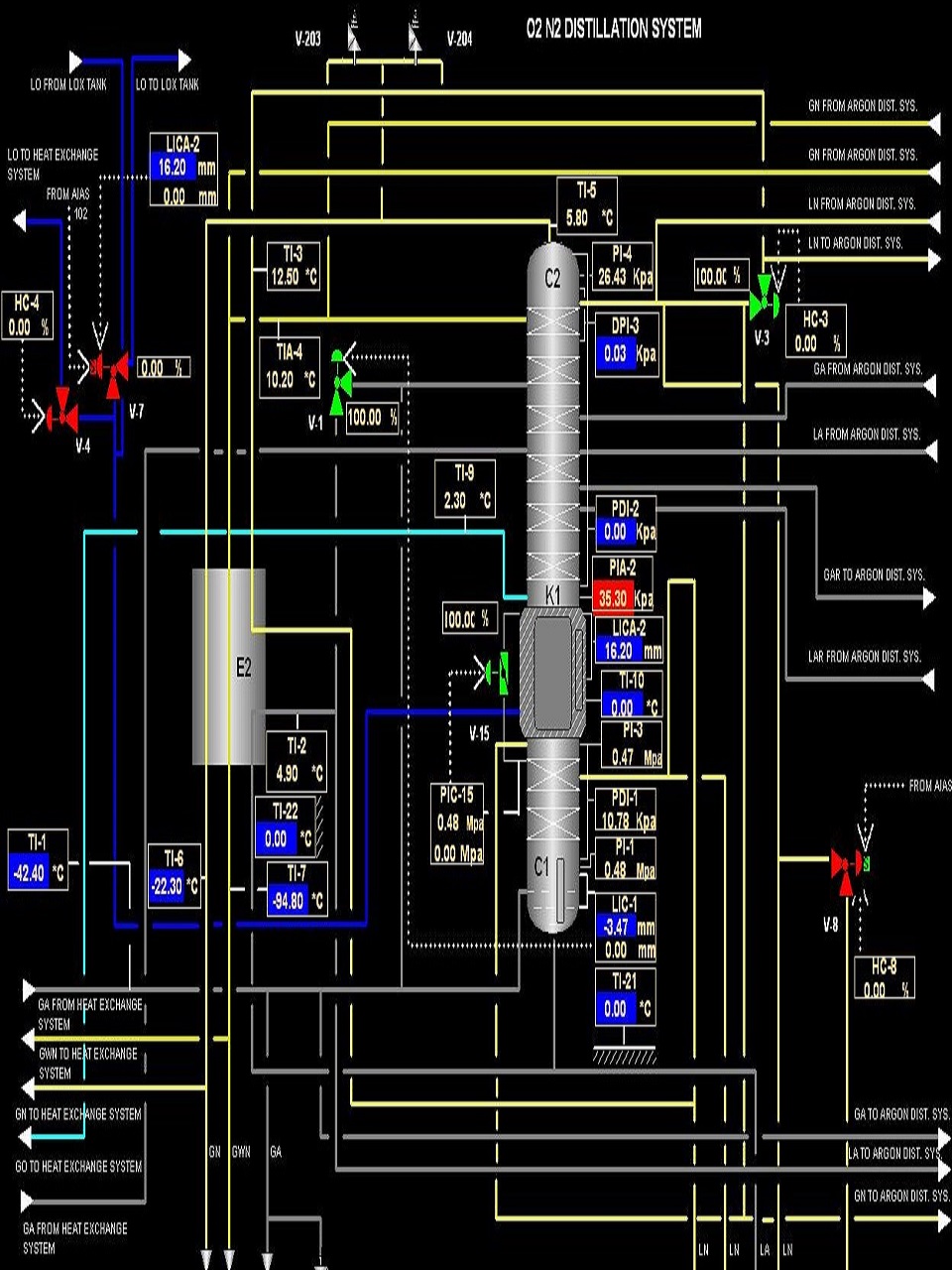


DCS control system is key part of ASU and consist of DCS and other control instruments to control process from computer.
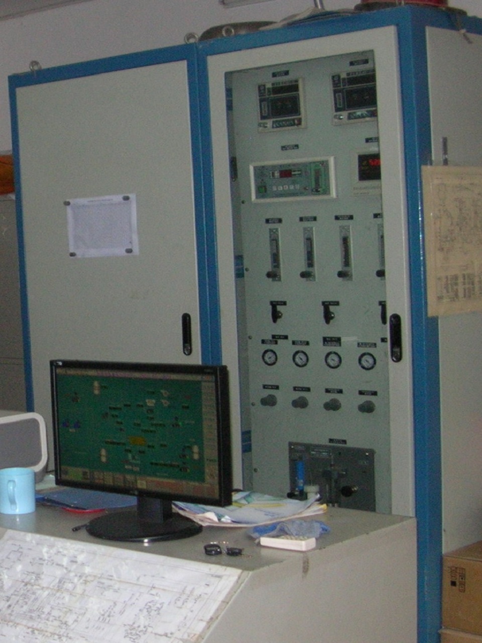


Gas Analyzer system is for Measuring of Gas purity and other parameters for requirements of ASU
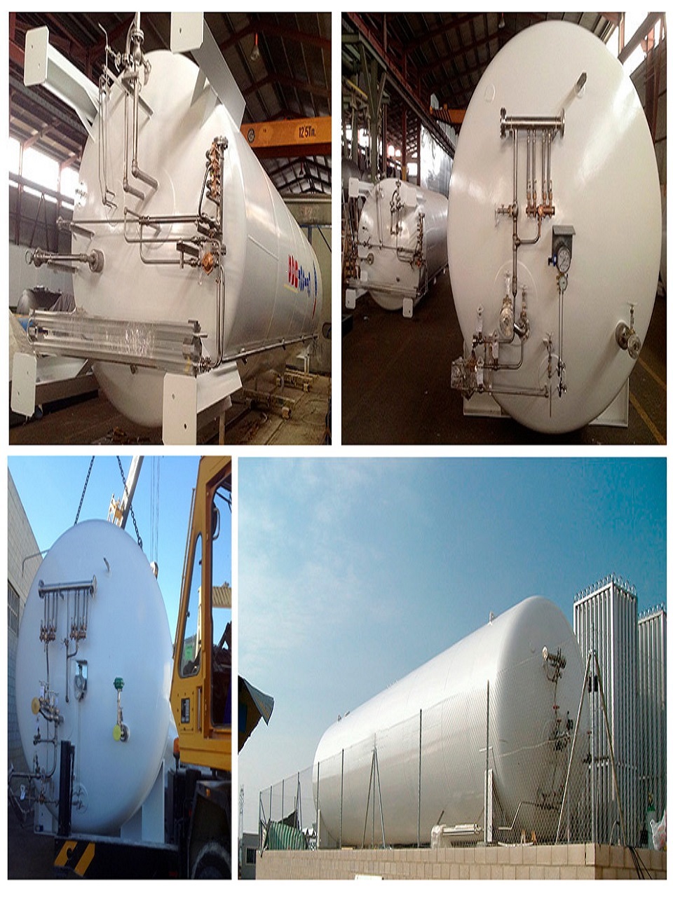


Other Components of ASU required for operational and maintenance is covered in this section Like as Storage Tank , Liquid Pumps , Liquid Storage Tank etc.